|
Q88
Instructions
|
|||||
 |
|||||
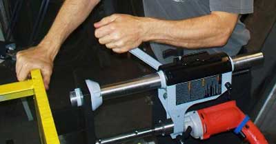
Instructions for using Q88-E line boring equipment from American Machine Tools Company. Re-Bores holes from 1 inch to 1.5 inch diameter.
ALWAYS WEAR SAFETY GLASSES! * ALWAYS
KEEP HAIR, CLOTHING, HANDS AND FINGERS CLEAR !
It is easier when you have an extra person to help with the setup. This
equipment is for reboring pivot holes up to 1.5" diameter in small earth
moving equipment such as Bobcats and other Skidsteers powered by your
variable speed drill with a 1/2 inch capacity drill chuck. If you are
using the Q88A add on option with your Q150 equipment, then please refer
to the Q150 instructions.
1. Using two holes to repair, insert one plastic
alignment cone against the good side of each worn hole.
2. Slide the 7/8 diameter boring bar through each cone and tighten
the set screws in the cones.
3. Bolt a self-aligning flange bearing to a bearing backup plate
using bolts and washers. Screw on 2 standoff plates with flat head screws.
4. Slide one bearing and plate on one end of the boring bar and
the drill press adapter (with built-in bearing) onto the other end. Screw
3" riser blocks to bearing plates and to drill press base. Determine where
riser blocks can be tack welded to connect bearing plates to equipment
to be line-bored. The 3" inch riser blocks allow easy removal of alignment
cones and access for cutting tool adjustment and measuring of the hole
with the digital caliper (a flashlight helps to see). Be careful not to
bend the boring bar with the weight of the drill press and bearing assemblies.
5. Tack weld all stand-offs to heavy equipment to be line bored
using many small tack welds to avoid warping.
6. Undo cone set screws, slide boring bar part way out and remove
the cones from under the bearing plates.
7. Slide boring shaft back through the bearing.
8. Add more bearings where possible to prevent vibration during
boring. We recommend at least one for every hole you wish to bore (unless
there are more than 3 holes).
9. After tack welding all the bearings in place it may be necessary
to loosen the bolts that hold the bearings to the plates (one bearing
plate at a time) and tap the boring bar slightly because the tack welding
may have warped the standoff plates, which can reduce the free movement
of the shaft through the bearings.
10. Insert the drill into the hole in the drill press flange and
tighten the black clamping screw lever. Carefully tighten the chuck of
your drill onto the 3 flats of the shank of the boring bar.
11. Insert cutting tool into boring bar. Start boring with the
cobalt steel cutter then try the carbide cutter. Use the set screw to
hold the cutter to proper dimension for cutting no more than a 1/64 inch.
12. Spray cutting oil or tapping oil in hole often. If you cant
get any cutting oil, WD40 can be used. Check often to make sure the drill
chuck is still tight on the shank.
13. Begin cutting at low RPMs. You should be able to remove up
to 1/64 per side with each pass. Keep the cutting tool bits at low RPMs
by using the Velcro strap to hold the trigger position on the drill.
14. Feed the boring bar forward by gently pushing or pulling on
the handle of the drill press attachment. If the cutting tool is fighting
hard, apply less pressure. The height of the drill press attachment can
be adjusted be loosening the black lever on the back of the drill press.
15. The left hand carbide cutting tools are for boring most types
of holes. The cobalt steel cutters are great to start with and also great
to finish with. They are easily sharpened. There are usually three options
to repair pivot holes on heavy equipment:
16A. Holes can be welded and then bored back to the original specs.
Unless you purchase a Bore Welder such as the BOA-308 this is time consuming
because it requires a lot of welding. Grind off or bore out galled metal
first to prevent weld hardening. Make sure you use the correct weld rod/wire
for reboring with carbide cutters. 6011 rod is easier to bore than 7018
but 6011 wears faster. For MIG wire use 70S6 or 70S2. Original Spec size
is the hole diameter specified by the manufacturer (such as Caterpillar)
to fit the pivot shaft pin, or if there is supposed to be a bushing, then
spec size is the hole sized to press fit the bushing.
16B. Holes can be bored larger than spec size, and then a sleeve
can be welded into the hole or an oversize bushing can be installed if
there was a bushing before. Then when the holes become worn out again
simply replace the old sleeve or bushing with a new one. They are easily
made on a lathe. Heat treat the sleeve to make it last longer.
16C. Bore to fit oversize bushings from a heavy equipment dealer
or an industrial bearing supplier.
17. Measure using digital caliper and inside caliper or optional
bore gage. To measure the cutting tool radius use the caliper from the
tip of the carbide to the backside of the boring shaft.
18. If you need perfection, consider honing the last .001 of an
inch of your holes.
19. When holes are finished, remove drill press assembly and bearings.
Use a torch and hand grinder to remove bearing standoff plates but only
when you are sure you are definitely done. NOTE: If you are careful you
should use about 2 cutters per hole set. Welded holes are hard on carbide
bits. Our standard equipment can bore up to about 1.5 inch diameter but
be aware that extending the cutting tool bit out very far increases unwanted
vibration (tool chatter). The carbide cutters can be modified or sharpened
with a green silicon grinding wheel mounted on a bench/pedestal grinder.
The cobalt cutters can be ground on a standard grinding wheel or belt
sander. If you get a clamping screw dent in the cutting tool shank you
can sand it smooth before re-adjusting tool height. All the cutting bits
come shipped to you at full length. Cut the shank of a cutting tool bit
with a hack saw to fit into your hole. To bore very small holes such as
1 inch diameter, you may need to grind back some of the carbide cutting
tool head to fit it down into the square tool holes.
ALWAYS WEAR SAFETY GLASSES! * KEEP HAIR, CLOTHING, HANDS AND FINGERS
CLEAR !

Click for Line Boring Machine webpage
Click for American Machine Tools Homepage
5864 Northwest Hwy
Chicago IL 60631 USA
Phone: 773-334-5000
Fax: 773-442-0314
Click to email us
Copyright © 2011
American Machine Tools Corp.
All rights reserved
Offers from American Machine Tools Corporation include include Terms and Conditions shown on our website.
Liability is strictly limited to those warranties of fitness for purpose and safety as provided by the manufacturer.
Products and Logos in this website are trademarks or registered trademarks of their respective companies or mark holders.